





In the transition towards Industry 4.0 and intelligent manufacturing, digital pressure switches have become the fundamental nervous system of automated fluid and pneumatic control loops. Unlike traditional mechanical gauges that simply display a visual reading, modern digital sensors actively monitor pipeline stability, execute instantaneous failsafe logic via discrete NPN/PNP outputs, and stream real-time data to central SCADA systems.
However, procuring a high precision digital pressure switch is only half the battle. The reliability, lifespan, and accuracy of these instruments are heavily dependent on proper mechanical installation, secure electrical wiring, and accurate digital calibration. A minor oversight during installation can lead to micro-leaks, electronic short circuits from fluid ingress, erratic signal bounce, or complete communication failure on your network bus.
This comprehensive, step-by-step engineering guide is designed for facility managers, automation technicians, and system integrators. It covers the entire lifecycle of installing a digital pressure controller, from pre-installation environmental checks to advanced networking, while highlighting the most common and costly mistakes made on the factory floor.
Phase 1: Pre-Installation Preparation and Environment Verification
Before a wrench ever touches the piping, rigorous preparation is required. Installing the wrong sensor in an incompatible environment is the leading cause of premature failure.
1. Verify Media Compatibility
Standard pneumatic sensors are strictly designed for filtered, non-corrosive, and non-flammable gases (like Clean Dry Air, Nitrogen, or Argon). If your application involves cooling water, hydraulic oil, or aggressive cutting fluids, you must verify that you are installing a Universal Fluid Type model featuring a SUS304 or SUS316 stainless steel diaphragm. Exposing a standard gas sensor to liquids will immediately destroy the internal piezoresistive chip.
2. Confirm Thread Standards and Port Sizes
Forcing mismatched threads is a catastrophic error. Confirm whether your manifold utilizes NPT, BSPT (R/RC), or Metric (M5) threads. If using push-in tube fittings, ensure the outer diameter of your polyurethane tubing perfectly matches the connector to prevent high-pressure blowouts.
3. Ambient Environment and IP Rating Checks
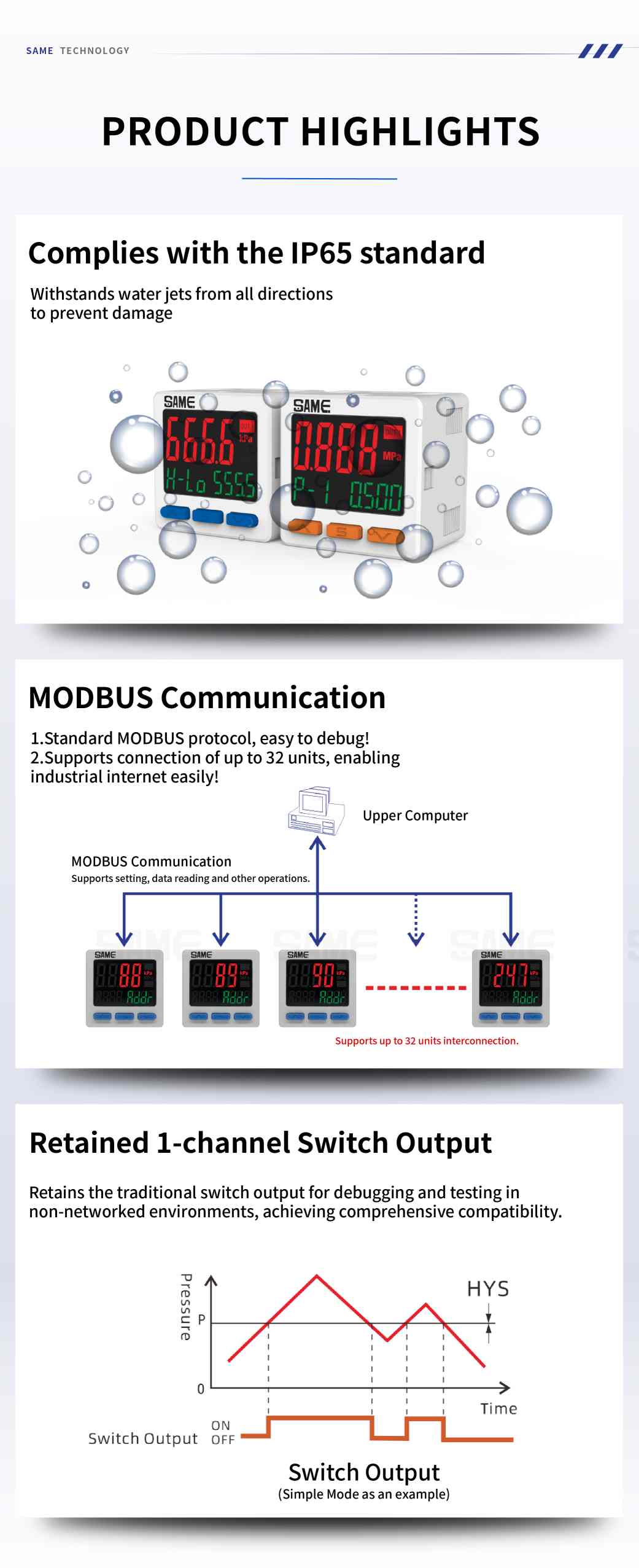
Check the operating temperature of the installation zone. If the sensor is being mounted in a CNC machining center or an active washdown zone, you must deploy an IP65 waterproof pressure controller. This strict ingress protection rating is required to repel multidirectional water jets and heavy dust. Standard indoor sensors will fail rapidly in these conditions.
Phase 2: Mechanical Installation and Piping
Mechanical mounting must be executed with precision. The goal is to achieve an absolute, zero-leak seal without exerting undue mechanical stress on the sensor's housing.
Step 1: Applying Thread Sealant Correctly
If your gauge uses taper threads, you must apply PTFE (Teflon) tape. Wrap the tape clockwise around the male thread 1.5 to 2 times. Always leave the first two threads completely bare. If tape overhangs the edge of the fitting, micro-shreds of Teflon will be sheared off during tightening, permanently clogging the sensor's microscopic inlet port.
Step 2: Wrench Placement and Torque
Never use the plastic display housing of the digital switch as leverage to tighten the gauge into the manifold. Doing so will shatter the housing or snap the internal circuit board. Always use an appropriately sized open-ended wrench strictly on the metallic hex nut at the base of the port.
Phase 3: Electrical Wiring and RS485 Integration
Wiring errors account for the majority of commissioning delays. Digital pressure switches typically utilize a 5-core cable for combined power, switching, and communication. Before stripping wires, power down the entire PLC and 24V DC bus.
1. Standard Power and Output Wiring
Strictly follow the color-coding specified in your manual. The Brown wire connects to the positive DC power supply, and the Blue wire connects to the negative. The Black wire is reserved for the primary discrete comparative output. Ensure your PLC's digital input module matches the sensor's logic: NPN (sinking) or PNP (sourcing). Crossing these will damage the internal transistors.
2. Shielding and Cable Routing
Never route the sensor's low-voltage DC cables in the same conduit as high-voltage AC power lines or VFD cables. Electromagnetic Interference (EMI) will induce severe noise on the analog lines and corrupt digital communication.
3. MODBUS RS485 Bus Topology
When integrating an RS485 modbus pressure sensor into a smart factory, connect the White wire (485A+) and Orange wire (485B-) to your network. RS485 requires a strict daisy-chain topology. Do not use a star or tree wiring layout, as this creates signal reflections.
Phase 4: Digital Calibration and Parameter Configuration
Once installations are verified, power on the system. The dual-screen display should illuminate, showing the current atmospheric pressure (which should be zero) and the default setpoint.
1. Atmospheric Zero-Clearing
Before introducing compressed air into the manifold, the gauge must be zeroed to account for local altitude and ambient atmospheric pressure. Ensure the pipeline is completely vented to the open air, then press and hold the designated zero-clear buttons until the main display reads exactly '0.00'.
2. Setting Comparative Output Modes
Navigate the UI to select your control logic. The most common settings are Hysteresis Mode and Window Comparison Mode. Hysteresis allows you to set a high trigger point and a slightly lower reset point, preventing the switch from rapidly fluttering when pressure fluctuates slightly near the threshold.
3. Adjusting Response Time
In turbulent fluid systems, instantaneous pressure spikes can cause false alarms. Access the advanced menu to increase the response time (selectable up to 5000ms). A slightly delayed response time acts as a digital filter, smoothing out temporary pressure ripples.
Common Mistakes to Avoid
- Installing at Dead Ends: Avoid installing the pressure gauge at the absolute end of a long, blind pipe run. Condensation and debris naturally accumulate at dead ends, blocking the sensor port.
- Ignoring Surge Pressures: Never select a gauge where the normal operating pressure equals the maximum rated pressure. Instantaneous valve closures create pneumatic shockwaves that rupture the sensor. Always ensure a 25% safety margin.
- Probing the Port: If a gauge seems clogged, never insert needles or wire into the pressure port to clean it. The internal piezoresistive diaphragm is microscopically thin and will be instantly destroyed.
Frequently Asked Questions (FAQ)
Q: How do I prevent water hammer damage during installation?
A: Water hammer, or severe pressure spikes caused by sudden valve closures, can easily rupture the sensor diaphragm. To prevent this, always install a pressure snubber (a restrictive orifice) or a coiled siphon tube directly before the gauge. Additionally, ensure your selected gauge range includes at least a 25% to 50% safety margin above your maximum expected operating pressure.
Q: What is the difference between gauge pressure and absolute pressure sensors?
A: A gauge pressure sensor measures pressure relative to the local ambient atmospheric pressure (which is why zero-clearing is required). An absolute pressure sensor measures pressure relative to a perfect vacuum absolute zero reference. For standard industrial compressed air, gauge pressure is the industry standard. Absolute pressure is typically reserved for specialized laboratory and meteorological applications.
Q: Why does my RS485 communication drop out intermittently?
A: Intermittent RS485 dropouts are almost always caused by electromagnetic interference (EMI) or improper network topology. Ensure you are using shielded twisted-pair cables and that the shield is grounded at one end only. Verify that you have not wired the network in a star topology, and confirm that a 120-ohm termination resistor is securely installed across the data lines at the furthest sensor on the bus.
Optimize Your Pneumatic Infrastructure
Executing a flawless installation guarantees years of ultra-precise, zero-maintenance operation. If you need assistance selecting the exact OEM specification for a complex new assembly line, contact our technical engineering team today for professional guidance.