





Quick Answer: A pressure drop in a pneumatic system usually results from air leakage, undersized pipes, clogged filters, an incorrectly adjusted regulator, insufficient compressor capacity, or excessive demand during actuator movement. To identify the real cause, measure pressure at the air source and at the point of use under both static and operating conditions. Comparing these readings helps distinguish supply problems from local restrictions and component faults.
Replacing a pressure gauge or increasing the compressor pressure without testing the system can waste energy and leave the original fault unresolved. A structured diagnosis is more reliable and helps prevent recurring downtime.
Key Takeaways
- Measure pressure at multiple locations instead of relying on a single gauge at the compressor outlet.
- Record readings at idle, during actuator movement, and under the heaviest normal load.
- Check filters, regulators, fittings, hoses, valves, and cylinders before increasing supply pressure.
- Investigate dynamic pressure drops even when the static pressure appears normal.
- Use suitable pressure sensors and control devices when continuous monitoring or automated correction is required.
1. Why Does Pneumatic Pressure Drop During Operation?
Compressed air loses pressure as it travels through pipes, fittings, filters, valves, and other components. Some pressure loss is unavoidable, but a sudden or excessive drop can indicate a fault issue or a system that was not sized correctly.
The distinction between static pressure and dynamic pressure is particularly important. Static pressure is measured when there is little or no airflow and the pipeline is closed. Dynamic pressure is measured while air is flowing and the equipment is performing work.
A machine may show 0.60 MPa at rest but fall to 0.45 MPa when several cylinders extend simultaneously. The 0.15 MPa difference suggests that the supply path cannot maintain the required pressure under that operating condition. It does not, by itself, prove that the compressor is undersized.
Potential causes include:
- Air leakage: Damaged seals, loose fittings, worn tubing, and leaking valves allow compressed air to escape.
- Flow restrictions: Dirty filter elements, narrow tubing, long pipe runs, and undersized fittings increase resistance to airflow.
- Regulator limitations: The regulator may be incorrectly adjusted, contaminated, or unable to deliver the required flow at the target pressure.
- Insufficient supply capacity: The compressor, receiver, or distribution network may not support simultaneous peak demand.
- Intermittent component faults: A sticking directional valve or damaged cylinder seal can create inconsistent movement and abnormal air consumption.
2. Measure Pressure at the Right Locations
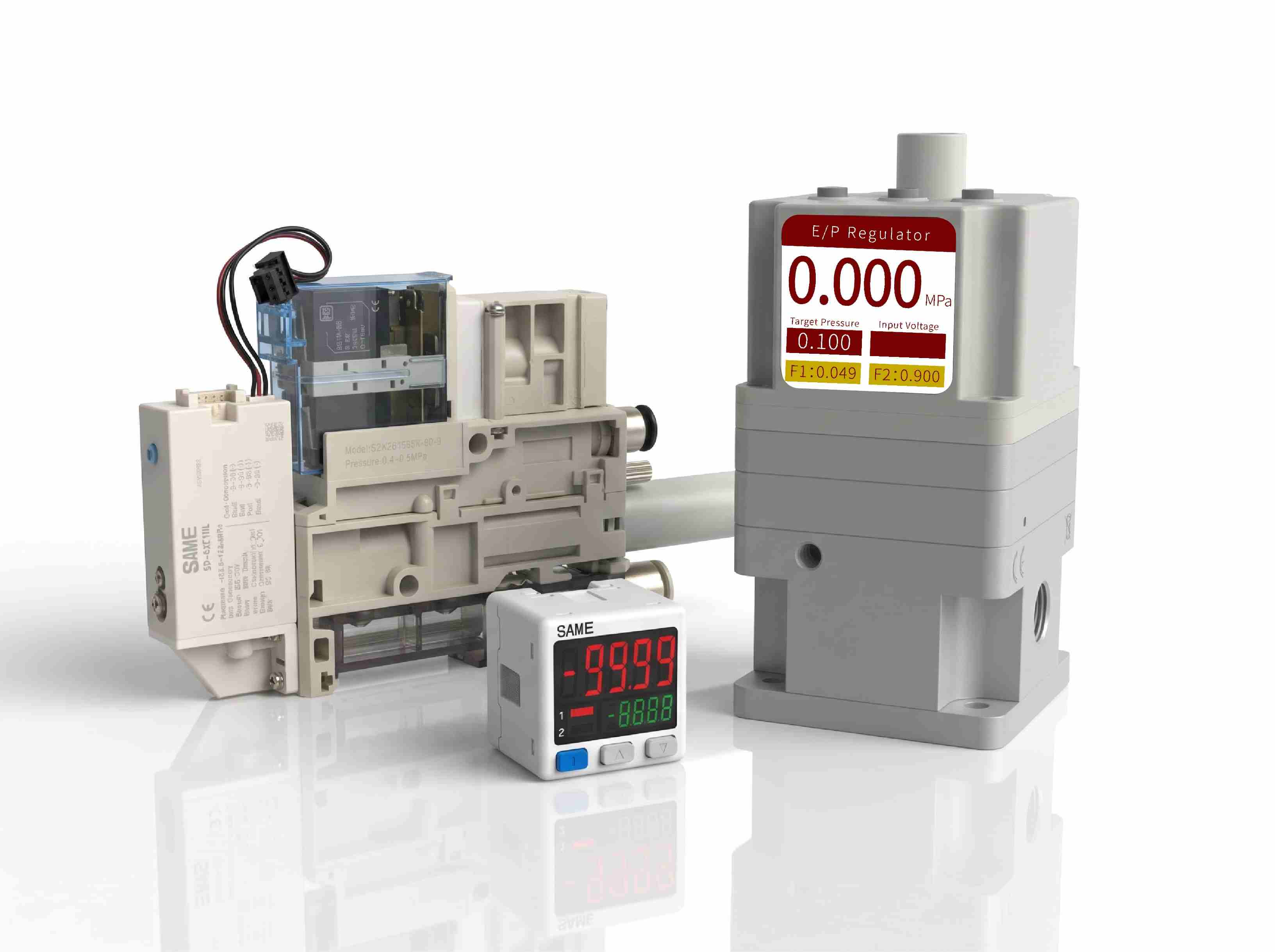
The most useful first step is to compare pressure readings at different points along the pneumatic circuit. Recording data at nearly the same instant is difficult to achieve with manual gauge reading; a digital pressure gauge with communication or analog output should be used. Taking the SAME SP15 series digital pressure gauge as an example, data polled from the host computer can achieve a reading speed on the 10 ms level.
For a typical industrial system, start with these locations:
- Compressor receiver outlet: Establishes the available supply pressure.
- Main distribution line: Shows whether pressure is being lost between the air source and the machine.
- Downstream of the filter and regulator: Identifies restrictions or regulator-related problems.
- Near the machine valve or actuator: Reveals pressure conditions at the actual point of use.
Record readings at the same time whenever possible. If the pressure at the receiver remains stable but the pressure near the actuator falls sharply, the fault is more likely to be within the distribution line, treatment unit, regulator, valve, or local tubing.
For repeatable monitoring, an Industrial Digital Pressure Gauge can make small pressure changes easier to observe. Select the measurement range, accuracy, connection, and output according to the application rather than choosing a device based on display resolution alone.
3. Use Pressure Readings to Narrow Down the Fault
A useful diagnostic record includes the operating state, upstream pressure, downstream pressure, and pressure difference. The following example illustrates how readings can guide further investigation.
| Test condition | Upstream pressure | Downstream pressure | Initial interpretation |
|---|---|---|---|
| Machine idle | 0.60 MPa | 0.59 MPa | Small pressure difference under low demand |
| One cylinder moving | 0.59 MPa | 0.55 MPa | Investigate flow resistance and regulator capacity |
| Multiple cylinders moving | 0.54 MPa | 0.43 MPa | Possible supply-capacity and local restriction problems |
Note: These are illustrative readings, not measured results from a customer installation. The acceptable pressure drop depends on the equipment manufacturer's requirements, flow rate, pipe dimensions, and operating conditions.
The pressure difference is calculated as:
Pressure drop = Upstream pressure − Downstream pressure
For the third test, the difference between the two measurement points is 0.11 MPa, or 110 kPa. That is a substantial change for many conventional pneumatic applications and warrants further investigation.
However, the reading alone cannot identify the defective component. Additional measurements across the filter, regulator, and distribution line are needed to locate where the pressure loss occurs.
4. Check Filters, Regulators, and Pipe Sizing
When the pressure drop increases with airflow, examine the components that create resistance along the supply path.
Filters: A clogged filter element can cause a significant pressure difference between its inlet and outlet. Measure both sides while the system is operating. Replace the element if its differential pressure exceeds the manufacturer's service limit.
Pressure regulators: A regulator's downstream pressure can decrease as flow demand rises. Compare its rated flow characteristics with the actual application. A regulator that performs well at low demand may not maintain the set pressure during simultaneous actuator movement.
Pipes and fittings: Small internal diameters, excessive elbows, long tubing runs, and restrictive quick couplings can increase pressure loss. Check the complete flow path rather than looking only at the main pipe diameter.
For applications that require changing the pressure setpoint automatically, an Electro Pneumatic Pressure Regulator can adjust the regulated pressure in response to an electrical command. SAME's published product range includes regulator configurations with pressure options of 0.1, 0.5, and 0.9 MPa, together with signal choices such as 4–20 mA, 0–20 mA, 0–5 V, 0–10 V, and RS485 communication on applicable configurations. These are product options, not universal operating settings; verify the exact model specifications before selection.
5. Find Air Leaks Without Replacing Good Components
Leakage can increase compressor runtime, reduce available flow, and make pressure control less stable. Begin with accessible fittings, tubing connections, valve manifolds, cylinder seals, and maintenance-unit joints.
With the equipment operating under an appropriate, safe test condition:
- Inspect connections for visible damage, loose fittings, and deteriorated tubing.
- Use an approved leak-detection solution or ultrasonic leak detector where appropriate.
- Listen for abnormal airflow only where doing so is safe; noise alone is not a reliable measurement.
- Isolate sections of the system using approved procedures to narrow down the leakage location.
- Repair the identified fault, then repeat the original pressure test under comparable conditions.
Never loosen a pressurized connection to check for leakage. Isolate and depressurize the relevant section before dismantling components, following the site's lockout and safety procedures.
6. Check Whether the Problem Is Actually a Vacuum Fault
Automated pick-and-place systems introduce another diagnostic challenge: a weak grip may be caused by inadequate vacuum rather than low positive air pressure alone.
Venturi vacuum generators use compressed air to create negative pressure. Their performance depends on the supply conditions, nozzle design, flow characteristics, leakage at the suction cup, and the workpiece's surface.
If a suction cup releases a workpiece unexpectedly, monitor both the compressed-air supply and the vacuum level near the gripper. A stable supply pressure with a deteriorating vacuum reading points toward a different set of possible faults than a supply pressure that falls at the same time.
For this type of application, a Compact Pneumatic Vacuum Generator may be suitable, depending on the required suction flow, target vacuum level, cycle time, and workpiece characteristics. The correct selection should be based on the complete gripping application, not maximum vacuum alone.
7. A Practical Troubleshooting Example
Consider a packaging machine whose pneumatic system pressure drops after a second actuator is added to the production cycle.
During the initial test, the pressure near the machine is 0.58 MPa at idle and falls to 0.44 MPa when both actuators move. The maintenance team initially suspects that the compressor is too small.
Instead of increasing the compressor's discharge setting immediately, the team compares pressure at the receiver, the maintenance unit, and the valve manifold. The illustrative readings below show how the investigation might proceed.
| Inspection point | Observation | Next action |
|---|---|---|
| Receiver outlet | Pressure remains comparatively stable | Check the downstream distribution path |
| Filter outlet | Pressure difference increases during flow | Inspect filter condition and rated flow |
| Valve manifold | Pressure recovers after demand decreases | Repeat dynamic testing and check local restrictions |
If a clogged filter or undersized connection is confirmed, correcting that restriction may restore cylinder speed without changing the compressor. If pressure also falls significantly at the receiver, investigate compressor delivery, receiver capacity, and the combined air consumption of the actuators.
This example is a diagnostic scenario, not a documented customer case. The important lesson is that measurements at several locations can prevent unnecessary equipment replacement.
8. Prevent Recurring Pressure Problems
Once the immediate fault has been corrected, establish a baseline for normal machine operation. Record upstream and downstream pressure, actuator cycle conditions, filter differential pressure where available, and the regulator setpoint.
Where pressure instability affects production quality, continuous monitoring can help maintenance teams identify changes before they cause a shutdown. Sensors with suitable analog outputs or industrial communication interfaces can feed readings into a PLC or supervisory control system, provided the electrical interface and pressure range are compatible.
For reliable monitoring, verify the sensor's pressure range, accuracy, response time, pressure port type, fluid compatibility within the pipeline, output signal, and environmental rating. Use the same measurement locations and comparable machine loads when evaluating trends. A rising pressure difference across one component is often more informative than a single pressure reading.
Frequently Asked Questions
Why does air pressure drop only when a pneumatic system moves?
When a cylinder moves, it consumes compressed air. A restricted pipe, clogged filter, undersized regulator, leaking component, or inadequate supply capacity may become apparent only when airflow increases. Measure pressure during movement to identify the affected section.
What is an acceptable pressure drop in a pneumatic system?
There is no single acceptable value for every machine. The limit depends on the actuator's minimum operating pressure, flow demand, component specifications, and the distance between the supply and the point of use. Establish an application-specific limit and verify it under peak operating conditions.
Will increasing compressor pressure solve the problem?
Not necessarily. Higher pressure may temporarily compensate for some losses, but it can increase energy consumption and place unnecessary stress on components. Locate the restriction or leakage first, then determine whether the supply capacity also needs improvement.
Can a digital pressure gauge detect intermittent pressure drops?
It can help if its response time, sampling capability, and measurement range are appropriate. For very brief fluctuations, confirm that the device can capture the event. A continuously monitored pressure sensor connected to a data acquisition system or PLC may be more suitable for recording fast changes.
How often should pneumatic pressure be checked?
Inspection frequency depends on operating hours, system criticality, air quality, and maintenance history. High-cycle production equipment may benefit from continuous monitoring, while less demanding systems may use scheduled inspections and baseline comparisons. Follow the equipment manufacturer's maintenance recommendations.
For industrial pneumatic applications, a repeatable pressure-testing procedure is more useful than repeatedly adjusting the supply setting. By comparing measurements at the source, across air-treatment components, and at the point of use, maintenance teams can identify pressure losses more accurately, restore stable actuator performance, and avoid unnecessary component replacement.