




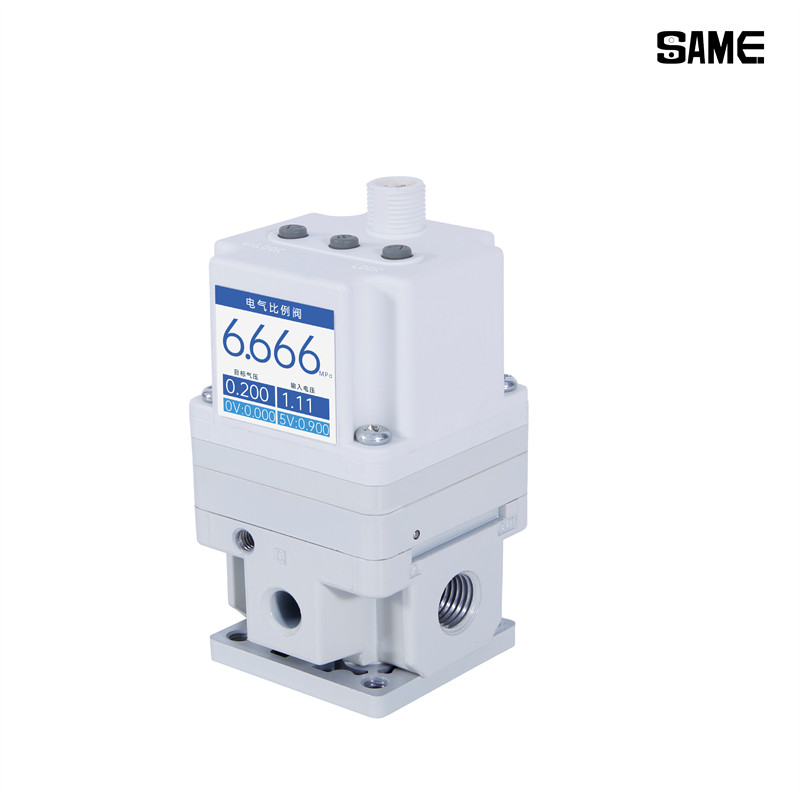
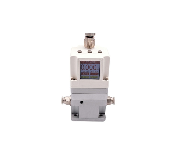
An electro-pneumatic regulator is a proportional device that delivers stepless control of air pressure in proportion to an electrical command signal. Manual adjustment relies on a knob or spring. The automated type of electro-pneumatic regulator replaces that mechanical input with a setpoint signal, so an operator or control system can adjust the output remotely.
Inside the unit, control electronics compare the command signal with feedback from an internal sensor and correct the output continuously. This closed-loop design holds the setpoint accurately under flowing and non-flowing conditions. Response is quick: SMC ITV electronic pneumatic regulators typically reach 90 percent of a step change in roughly 0.5 to 1 second, negligible for slow fill cycles lasting minutes.
Key Takeaways
-
An electro-pneumatic regulator controls air pressure precisely using an electrical signal instead of a manual knob.
-
It works in a closed loop: a sensor measures pressure and the device adjusts continuously to hold the setpoint.
-
You get fast response, remote control, and fail-safe options that mechanical regulators cannot match.
-
These regulators suit automated lines that need accurate, repeatable pressure control, such as web tension or semiconductor processes.
-
Choose the right signal type and pressure range for your application to ensure optimal performance.
What Is an Electro-Pneumatic Regulator
Definition and Core Function
An electro-pneumatic regulator is a proportional regulator that controls pressure steplessly in proportion to an electrical signal. The device uses a proportional solenoid or voice-coil actuator to hold an output pressure that follows a low-level analog command signal. A mechanical unit depends on a spring-loaded diaphragm and a fixed mechanical reference. The electronic type works as a closed-loop servo system instead. An internal pressure sensor feeds data back to a controller, and the controller drives a supply valve and an exhaust valve. These two servo valves regulate the pressure in a pilot chamber, and that chamber acts as a virtual spring on the main plunger. Engineers often describe this arrangement as a proportional pressure control valve with closed-loop feedback.
The I/P transducer distinction matters here. An i/p transducer converts a current signal into proportional pneumatic pressure, where "I" stands for current and "P" stands for pressure. The electro-pneumatic regulator is the broader device that uses this conversion. An electro-pneumatic transducer, an e/p transducer, a current / pressure transducer, and a voltage / pressure transducer all describe that same signal conversion stage. Electro-pneumatic pressure regulators are distinct from mechanical pressure regulators, pneumatic safety regulators, mass flow control valves, and pressure transducers. A pneumatic pressure regulator with a spring still suits simple local duty. Electro-pneumatic pressure regulators serve automated duty instead.
Key Components
Four building blocks appear in most designs. The proportional solenoid or voice-coil actuator moves the valve element in response to coil current. A sensing element provides the feedback signal for the loop. Control electronics compare command and feedback, then correct the drive signal. The valve body contains the supply and exhaust paths that set the output.
Supporting parts vary by model:
-
An electro-pneumatic pilot valve with a built-in amplifier needs only an external 24V DC supply and a 1–5V DC signal voltage.
-
A solenoid valve paired with a regulator forms a hybrid unit, such as the VY1 series.
-
An internal spool assembly moves infinitely to raise or lower the flow or the released air.
-
An LED display and monitor output give local readout, with analog or switch output available.
Command signals follow common industrial conventions:
|
Device / Series |
Supported Input Signal Types |
|---|---|
|
SMC ITV series |
4-20mA or 0-10V (selectable) |
|
AutomationDirect I-Z-P |
4-20mA only |
|
Chelic CVTR series |
Current: 4-20mA; Voltage: DC 0-5V or DC 0-10V |
|
General PLC analog control |
4-20mA (preferred, fault-detectable) and 0-10V (simple, noise-susceptible) |
|
Network protocol options |
MODBUS TCP, EtherNet/IP, PROFINET, EtherCAT (via gateways/fieldbus) |
A 4 – 20 ma loop suits long cable runs because the live zero reveals a broken wire. Voltage signals serve short, clean installations. Electronic pressure controllers and electronic pressure regulators often accept both ranges. The integrated electronic control system handles scaling and filtering inside the housing. Electronic control at this level removes the manual knob from every drop. Electro-pneumatic control also draws compressed air only as needed, and electropneumatic designs save energy elsewhere in the pneumatic system.
How Electro-Pneumatic Pressure Regulators Work
The Electro-Pneumatic Control Loop
The loop runs in a fixed sequence, and each stage hands off to the next:
-
A PLC or controller sends a command signal, commonly 4–20 mA or 0–10 V, to the unit.
-
Control electronics scale that signal into a setpoint and compare it with live feedback.
-
A proportional solenoid or voice-coil actuator strokes the pilot supply and exhaust valves.
-
The pilot chamber shifts the main plunger, which adjusts flow through the valve body.
-
A pressure sensor measures the result and returns an electrical feedback signal.
-
The controller computes the deviation and corrects the drive signal, and the cycle repeats continuously.
The pressure sensor is typically a silicon strain gauge or MEMS element referenced to atmosphere. It reads the actual regulated pressure many times per second. An embedded PID controller compares that reading against the setpoint and decides how far to move the pilot valves. A normally-closed supply valve admits upstream air into the pilot chamber. A normally-closed exhaust valve bleeds it. This arrangement gives stepless adjustment from a single analog wire, and engineers sometimes describe the whole assembly as a closed-loop pressure control valve — learn more about our proportional regulators.
Regulated Pressure Output
The primary function is to hold a stable output pressure whether air is flowing to the load or the line is dead-ended. Under flow, the regulator must compensate for the pressure drop across downstream components. Under no-flow conditions, it must resist creep and drift. Both cases rely on the same feedback correction.
One behavior deserves attention during commissioning. When primary pressure first reaches the inlet, a minimum pressure appears at the outlet port even with a zero command. This offset is normal for the design, and the command span starts from that floor. A 0–10 V signal mapped to a 1–145 PSI range illustrates the scaling: the low end of the command corresponds to the minimum, and the high end corresponds to full span.
Closed-loop accuracy is the payoff. The loop corrects continuously so a technician can trust the setpoint shift after a command change, and the loop settles quickly rather than hunting. Fast response comes from the short sensing path and the direct-acting pilot valves, not from complex math. In practice, the electronics do the correction work, and the mechanic never touches a knob.
Benefits and Comparisons
Advantages of Electro-Pneumatic Control
Electronic setpoint control delivers precision a knob cannot match. High precision electronic pressure regulators hold accuracy to ±0.2% of full scale, and the loop corrects continuously for accurate and repeatable pressure control. A PLC changes the setpoint remotely, so one operator adjusts many drops without walking the line. Response is fast, and the stepless output pressure removes the jump between fixed spring settings. Electronic control also trims compressed air use, because the unit supplies only what the process needs.
Fail-safe behavior deserves a close look. The table below summarizes two common loss scenarios.
|
Failure Condition |
Regulator Behavior |
Resulting Output |
|---|---|---|
|
Control signal lost (below ~50 mV), supply power present |
Exhaust valve opens |
Output drops to 0 PSI |
|
Supply power lost and signal lost |
Both internal valves close |
Downstream line held at last setpoint |
IO-Link communication simplifies installation further. An M12 cable replaces analog I/O cards and screw terminals, and the master downloads parameters automatically. Standard applications typically need no reset of factory settings after a device swap. Real-time diagnostics flag a disconnected wire before it stops production, and commissioning time drops.
Compared with a Pneumatic Pressure Regulator
Each regulator type fits a different job. A mechanical pneumatic pressure regulator costs little, needs no power, and suits simple local adjustment. Electro-pneumatic control suits precise, remote, or automated duty. For remote setpoint control for automated pneumatic lines, the electronic type is the practical choice. Shenzhen Same Technology Co., Ltd. supplies both families, so buyers can match the technology to the task.
Electro-pneumatic pressure regulators also report data. Electronic pressure controllers and smart positioners feed live readings back to the control room, and technicians spot drift without a field visit. A pneumatic system pressure change at the header reaches the electronic unit as a disturbance the loop corrects. A pneumatic pressure regulator simply follows it. Both approaches remain valid; the choice rests on how much control and visibility the pneumatic system requires.
Common Applications
Typical Use Cases
Electro-pneumatic pressure regulators appear wherever a machine must change force or pressure without stopping. Web tension roll control in pulp and paper mills is a classic case. The unit holds a steady force on the roll as the web diameter changes. OEM equipment builders also integrate these devices into automated machinery alongside FRLs, air relays, volume boosters, and cylinders. Controlled Pneumatics describes the same pattern: proportional valves, sensors, and algorithms work in a closed loop, and flow control valves set the speed of cylinders and grippers for smooth, infinitely variable motion.
Semiconductor work demands tighter numbers. Closed-loop electro-pneumatic regulators control polishing pad pressure in chemical mechanical planarization. Sputtering tools hold tight pressure tolerances so the coating lands evenly and protects delicate wafers. Vacuum and flow control for process chambers and precision cleaning systems follow the same logic. Test stands and electronics manufacturing rely on stepless air or vacuum adjustment with analog or switch monitor outputs. Vendor pages for test and analysis markets state that precise pneumatic control solutions serve testing, building, or polishing delicate electronic components. Packaging lines use the same hardware for consistent clamp and seal force.
Sizing and Selection Factors
Engineers should start with the required pressure range and the flow capacity the load demands. The input signal type comes next: 4–20 mA for long runs, 0–10 V for short, clean cabinets. Accuracy and response time follow from the process, and communication options such as IO-Link simplify commissioning and device swaps. Fail-safe behavior deserves a decision of its own, because signal loss and power loss produce different outputs. A proportional pressure regulator selection guide helps match these factors to a model. Shenzhen Same Technology Co., Ltd. supplies both mechanical and electronic families, so buyers can weigh control needs against budget. Technicians and hobbyists should confirm ambient temperature, vibration, corrosion exposure, and bowl material before ordering.
An electro-pneumatic regulator is an electronically controlled device that converts a command signal into proportional air pressure. A command signal reaches the control electronics, and an actuator strokes the valve. The valve adjusts output pressure, and a sensor returns feedback so the loop corrects itself continuously. Users gain precision, remote setpoint control, fast response, and fail-safe options. This electro-pneumatic control fits automated lines that demand accuracy. Electronic pressure regulators suit remote duty, while mechanical pressure regulators serve simple local adjustment. Buyers should match the regulator type to their control, accuracy, and budget needs. One regulator choice rarely fits every drop, so compare options before ordering.
FAQ
How does an electro-pneumatic regulator differ from an I/P transducer?
An I/P transducer converts a current signal into proportional pneumatic pressure. The regulator is the wider device. It contains that conversion stage plus a sensor, control electronics, and a valve body. The complete unit holds a set output pressure in a closed loop.
What happens when the command signal or power is lost?
Behavior depends on the failure. A lost signal with supply power present opens the exhaust valve, and output pressure falls to zero. A full power loss closes both internal valves, and the downstream line holds its last setpoint. Engineers should confirm the fail-safe mode before installation.
Does the device hold pressure when downstream air stops flowing?
Yes. The control loop corrects against sensor feedback under flowing and non-flowing conditions alike. Dead-ended service resists creep and drift, so the setpoint stays stable after the load stops.
Which command signal should a designer specify?
A 4–20 mA loop suits long cable runs, because the live zero reveals a broken wire. Voltage signals such as 0–10 V serve short, clean cabinets. Many pressure regulators accept both ranges, and models like the SMC ITV series allow selectable 4–20 mA or 0–10 V input.
Can one unit cover a wide output range?
The command span starts from a minimum outlet pressure present whenever primary pressure reaches the inlet. Scaling maps the low end of the signal to that floor and the high end to full span. Designers should size the range to the process, not to the widest available option.